Back to home page
Back to photography main page
Back to equipment page
Back to lab software page
![]()
![]()
![]()
Dark Tools Hardware Interface |
Help us to continue the development of this tool by your donation: |
This hardware interface drives one or more enlargers.
It integrates a measure of light in both quantity and quality aspects (RGB sensor).
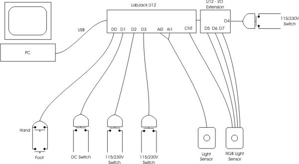
The software installed on the PC (Windows 98 SE or more recent because of the USB interface) drives the LabJack via the USB interface. The LabJack drives then the digital inputs/outputs (I/O ports) or the analog inputs/outputs. The LabJack has only 4 digital I/O on the screw terminals, you must add the extension via the DB25 connector to obtain the other digital I/O channels.
Electrical supply for the LabJack and the surrounding circuits is supplied by the PC via the USB port. Some circuits also use the main supply.
This interface was chosen for the following reasons:
All informations are available on LabJack website: http://www.labjack.com
Don't forget to install the LabJack drivers (ljackuw.dll), if you don't want to develop around the LabJack, download the executable "drivers only" from LabJack's website download page: http://www.labjack.com/downloads.html
In case the website is not available, here is the documentation and software:
An OEM version without connectors does also exist.
It is not impossible that, in a few months, a commercial version will appear for
photographers that are not confident with a soldering iron.
If this does interest you, don't hesitate to tell it, this brief opinion poll
will help me decide if there is a commercial interest or not.
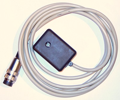
The software is normally driven by the keyboard/mouse but hands being often used for other tasks, an external footswitch (and/or doubled by a hand pushbutton) can launch the timers.
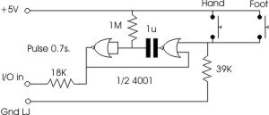
As we cannot trigger a Windows event through the LabJack, the software
checks, every 100ms, the logical state of the digital I/O port connected to the
footswitch. As there may be cases where the photographer hits the switch between
two checks, the circuit simulates a longer pressure on the switch allowing the
software to capture it.
The circuit is a monostable trigger based on a logical NOR chip producing a
pulse width of around 700ms or 0.7s, the software can easily see this pulse.
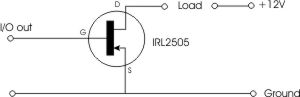
This switch is intended to drive directly the bulb of low voltage enlargers.
Warning: this switch must only be used with continuous current (DC).
This is the type of switch I use with the stabilized power supply for the Focomat
V35.
This circuit uses a more modern component than the classic relay, a power
Mos-Fet intended for switching use.
The choice of this component is pretty sensitive, the IRL2505 shows several
advantages for our application:
A cold filament has a much lower resistance than hot, so a high inrush current occurs when switching on and may be (usually is) large enough to activate the supply protections. Depending of the supply protection scheme this may not work properly.
I use a switching stabilized supply for my V35, you can find important informations on the stabilized supplies page explaining the inrush current problem when switching on lamps and the ways to remedy it.
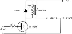
A classic relay-based schematic, this one uses the bulb power supply as
supply for the relay coil.
The transistor lets us connect the relay to the TTL-level output allowing only a
small current. The choice of this transistor is not critical.
A schematic close to the previous one but allowing to switch a main supply or
any other DC voltage.
A separate supply is needed to drive the relay coil.
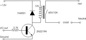
This schematic drives an enlarger with a 230V bulb or a low voltage bulb
feeded by a transformer.
This kind of circuits exists integrated in a single case, they are called solid state
relays (available at Crydom and others) but are not very cheap.
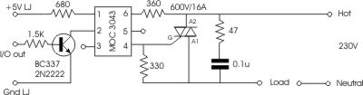
An optocoupler (MOC3043) separates the two circuits and avoids to inject high
voltage into the LabJack and/or the PC. Insulation between low and high voltage
circuits is around 7500V
The low voltage circuit drives an internal LED positionned right in face of a
light sensor that drives an internal TRIAC which drives the external power TRIAC.
The MOC3043 has also the interesting property of switching ON and OFF only when
the sinus wave passes through zero favoring a longer bulb life.
Transistor BC337 (2N2222 or others may be used but check the wiring diagram) is used as current source for the internal LED of the MOC3043.
The external TRIAC is a standard model (BTB 16-600B) allowing 16A under 600V.
Warning, the last "B" of the description means the heater is
electrically connected to the hot side of the mains: do NOT touch it when
connected to the mains !
A snubber circuit is also added (47 Ohms resistor + 0.1uF cap, in my
realization, it is replaced by an integrated RC network in a single case).
Datasheet MOC3043M
Datasheet BC337
Datasheet 2N2222
Datasheet BTB16-600B
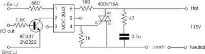
The schematic is nearly identical to the 230V but, the voltage being lower, two resistors values are modified.
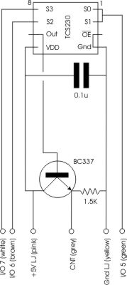 |
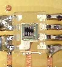
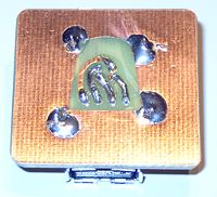
This sensor is based on component TCS230D from TAOS Inc.
that generates a square wave which frequency is proportional to the
light's intensity. This component is constituted by a 8x8 matrix of sensors, 16 per color: red, green, blue and white. TTL inputs allows color selection and output frequency ranges (internal dividers). This component is a SMD type and should be soldered on copper side. Tests are going well but aren't completely finished yet. Transistor BC337 (or 2N1711 but printed board should be modified) allows a lower output impedance and longer cables
|
|||
|
|
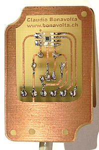 The TCS230D welded on copper side |
 The components side: so few things ! |
||
|
|
||||
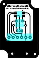
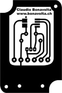
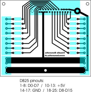
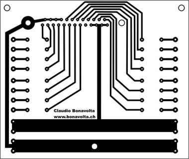
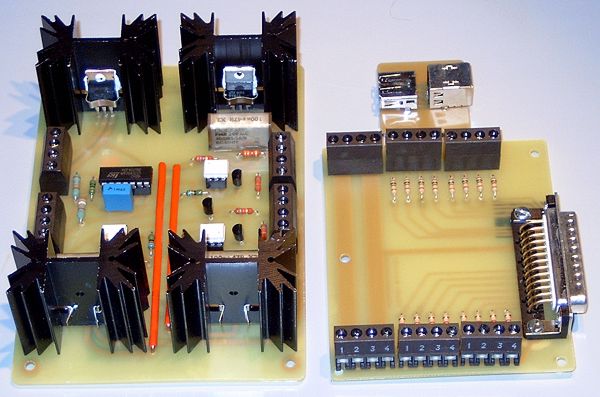
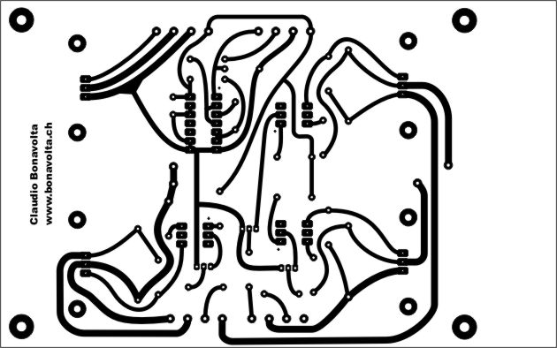
The layout (seen from components side) below groups following functions:
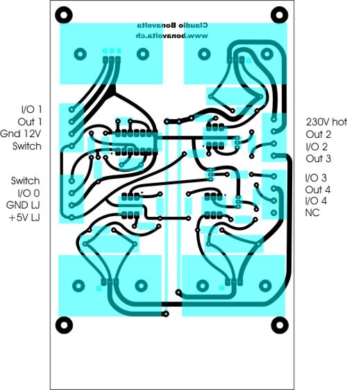
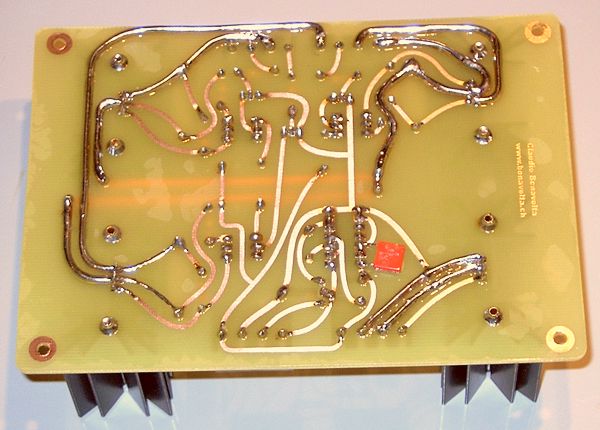
Original size of printed board is 160x100mm (6.3"x3.9"). Following reproduction is done at 100dpi.
I've doubled all high-current tracks with a copper wire directly soldered on them, probably an excessive precaution ...
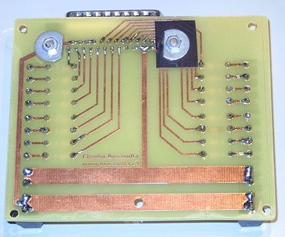
The LabJack U12 has only 4 digital inputs/outputs on the screw terminals, the other are available via the DB25 connector. To access them easily we need an extension including other screw terminals.
This extension is available at LabJack under reference CB25.
Here is a somewhat simplified home-made version. It does include the ports
protection resistors (1.5K).
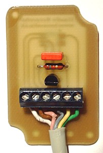
Components Insertion |
Printed Board (100dpi) |
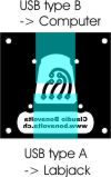
Except the OEM versions, the LabJack U12 is supplied is a case with screw
terminals, USB and DB25 connectors for the I/O extension.
This is very agreable in laboratory tests, somewhat less if you want to include
it in another case for a finished product, because of the USB connector that
must be deported to the outside case.
I've used two USB connectors for printed board, the first of type A (connections in line) to the LabJack and the second of type B (connections in square) to the PC.
Components Insertion |
Printed Board (100dpi) |
|
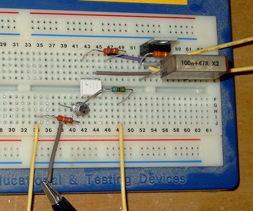
Test of the 230V switch on a bread board.
|
|
Components soldered on the printed boards
|
|
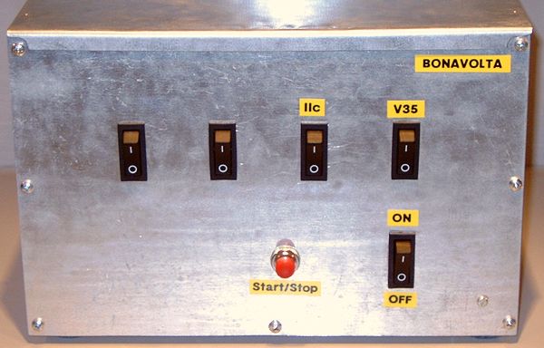
Front panel with the main switch (right) and the hand switch driving the timers (center)
|
|
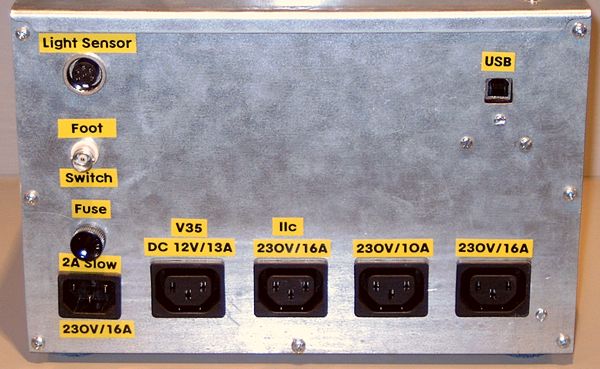
Rear panel with, from left to right and up to down:
|
|
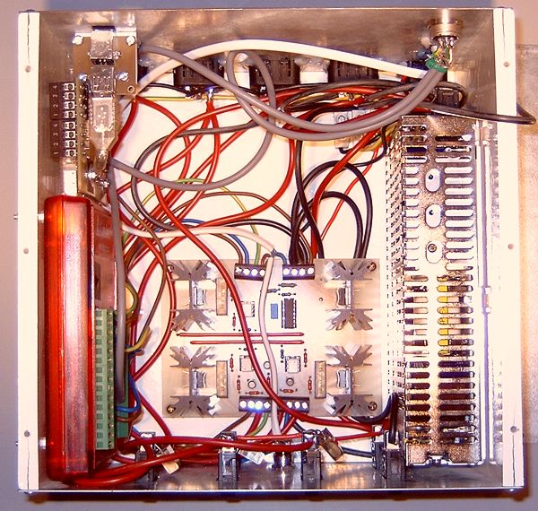
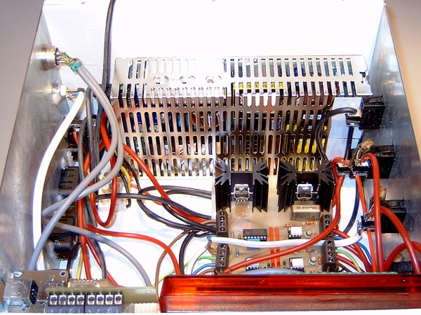
Inside the box:
|
|
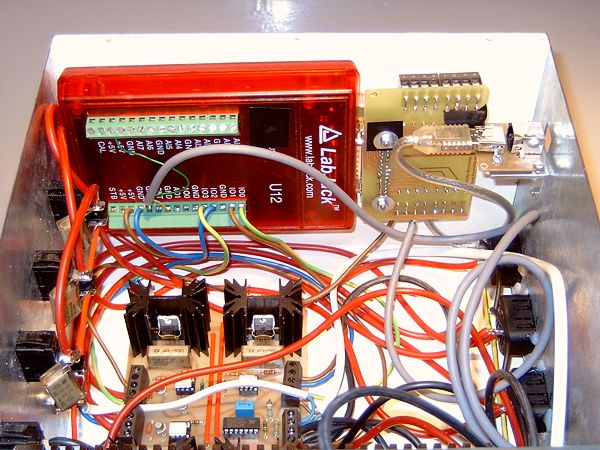
The LabJack, its I/O extension and the USB connector.
|
The 12V stabilized switching supply.
|