Back to home page
Back to audio
electronics page
Back to initiation page
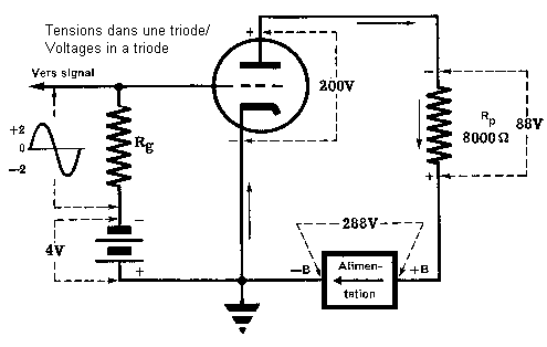
Biasing a tube is nothing else than produce the various voltages it needs to work properly. Mainly the constant control grid voltage added to the input signal. This voltage is extremely important to fix the mid-point where the tube is the most linear.

Here is an example of the various voltages around a tube.
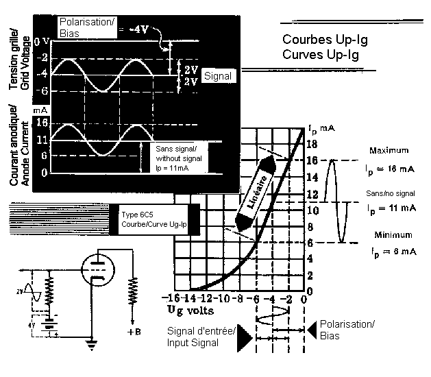
The biasing voltage sets the working point of the tube ideally in the middle of the linear part of its curve.
Here are some fixed biasing examples where a constant voltage is produced and applied to the grid and an example of an automatic biasing technique.
 |
Biasing using a battery. Not very common. |
 |
Biasing using a generator. Never seen ... |
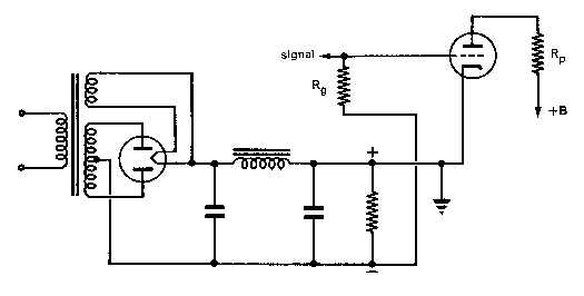 |
Biasing through the power supply. Very common. |
 |
Adjustable biasing through the power
supply. Not very common. |
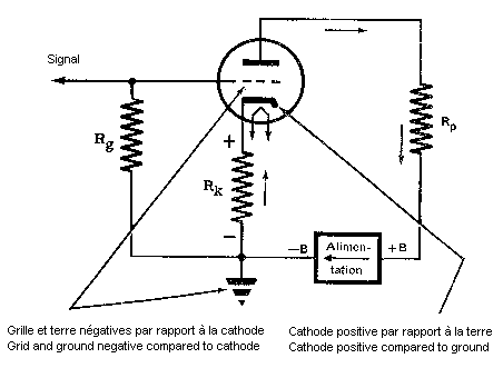 |
Automatic biasing Very common. Instead of making the grid negative, the cathode is set to a positive voltage which makes the grid negative to the cathode. this effect is obtained by adding a cathode resistor. Because of the current flowing through this resistor, a voltage difference appears between the cathode and the ground, this voltage should be identical to the biasing voltage needed. |
One remark, the cathode to plate voltage of the tube is no
more identical to the power supply voltage, we should diminish it
by the bias voltage.
Mixed biasing. It's possible to mix the two modes of biasing,
even though it's not very current.
For a triode:
![]()
where Ubias = desired bias voltage
Ip
= plate current
For a tetrode or pentode, we must not forget the current flowing through the screen grid:
![]()
where Ubias = desired bias voltage
Ip
= plate current
Ie
= screen current
Some tubes have a control grid current, you should add it to the total current.
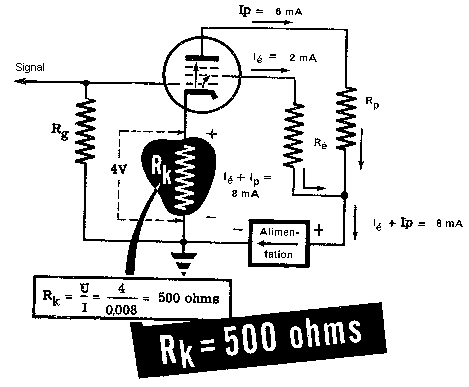 |
An example of automatic biasing. |
This system has a drawback. The variations of the plate current due to the control grid voltage changes gives a variation of the voltage at the cathode resistor, thus the bias voltage. This variation is in phase opposition with the input signal and reduces it. It's a form of a negative feedback.
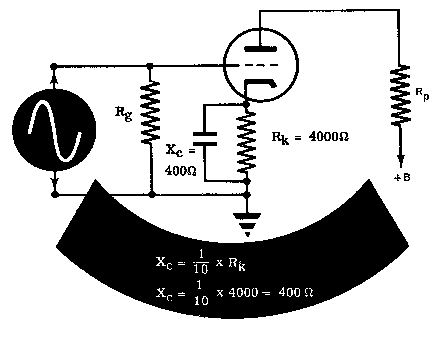 |
A decoupling capacitor allows to
stabilize the bias voltage. The value is usually high for a good stabilization and a lower bandwidth because the AC part of the current flowing through the tube will pass through this cap. The quality of this cap should be high for this same reason. |
A usual rule sets the capacitor reactance at the lower frequency to be reproduced at an 1/10 of the cathode resistance. Of course, you can use a larger one.